产品详情
详情介绍:IS200VAICH1GBA VME模拟输入/输出(VAIC)板
规范
零件号:IS200VAICH1C
制造商:通用电气
系列:马克六世
产品类型:模拟输入/输出板
功能:VAIC处理器板
通道数量:24个通道(20个AI,4个AO)
供货情况:有现货
原产国:美国
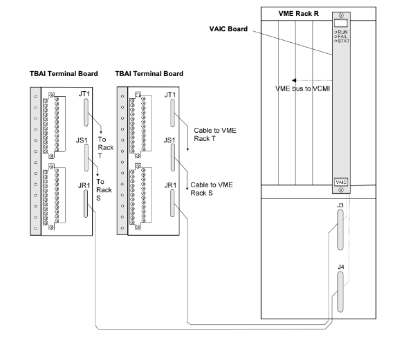
IS200VAICH1C是通用电气公司制造的VME模拟输入/输出(VAIC)板,是燃气轮机控制系统中使用的Mark VI系列的一部分。模拟输入/输出(VAIC)板接受20路模拟输入并控制4路模拟输出。每个端子板接受10个输入和2个输出。电缆将端子板连接到VAIC处理器板所在的VME机架上。VAIC将输入转换为数字值,并通过VME背板将其传输到VCMI板,然后传输到控制器。对于输出,VAIC将数字值转换为模拟电流,并通过端子板驱动这些电流进入客户电路。VAIC支持单模块和三模块冗余(TMR)应用。在TMR配置中使用时,端子板上的输入信号分散到三个VME板机架R、S和T上,每个机架都包含一个VAIC。输出信号由专有电路驱动,该电路利用所有三个VAICs产生所需的电流。如果发生硬件故障,坏的VAIC将从输出中移除,其余两块电路板继续产生正确的电流。当在单工配置中使用时,端子板向单个VAIC提供输入信号,后者为输出提供所有电流。
和睦相处
有两代配有相应端子板的VAIC板。原始VAIC包括VAICH1C之前的所有版本。VAICH1B包含在这一代产品中。当驱动20 mA输出时,这些板在1000英尺的#18线末端支持高达500的负载电阻。这一代电路板需要TBAIH1B或更早版本的端子板才能正常工作。它们还可以与DTAI端子板的所有版本一起正常工作。最新的VAICH1D和任何后续版本旨在为20 mA输出驱动电压支持更高的负载电阻:端子板螺钉端子处最高可达18 V。这允许在负载为800的情况下使用1000英尺长的18号线进行操作,并留有余量。这一代主板需要TBAIH1C或更高版本,或者STAI的任何修订版。
装置
- 关闭VME处理器机架的电源
- 滑入主板,用手推入顶部和底部拉杆,以固定边缘连接器
- 拧紧前面板顶部和底部的自持螺钉
操作
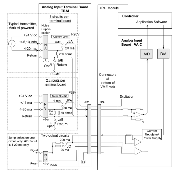
VAIC板接受20路模拟输入,控制4路模拟输出,并包含信号调理、一个模拟多路复用器、一个模数转换器和一个数模转换器。模拟输入的类型,电压4-20 mA或端子板。四个模拟输出电路中的两个为4-20 mA,另外两个可配置为4-20 mA或0-200 mA。输入和输出具有噪声抑制电路,可防止浪涌和高频噪声。
在TMR系统中,模拟输入从JR1、JS1和JT1分散到三个控制机架。传感器的24 V直流电源来自所有三个VME机架,由二极管供电或在端子板上选择。每个模拟电流输出由所有三个VAICs的电流供电。实际输出电流由一个串联电阻测量,该电阻向每个VAIC反馈一个电压。结果输出是三个电流的投票中间值(中值)。下图显示了TMR安排中的VAIC。变送器/传感器可以由控制系统中的24 V直流电源供电,也可以独立供电。诊断监控每个输出,如果处理器的命令无法清除故障,自杀继电器会断开相应的输出。端子板上的硬件滤波器抑制高频噪声。VAIC上的附加软件滤波器提供可配置的低通滤波。
压缩机失速检测
VAIC固件包括燃气轮机压缩机失速检测,以200 Hz执行。有两种失速算法可供选择。两者都使用前四路模拟输入,以200 Hz扫描。一种算法用于小型LM燃气轮机,并使用两个压力传感器(参考图中的小型(LM)燃气轮机压缩机失速检测算法)。另一种算法适用于重型燃气轮机,使用三个压力传感器(参见图中的重型燃气轮机压缩机失速检测算法)。为清晰起见,实时输入与配置参数分开。参数CompStalType选择所需的算法类型,两个或三个传感器。PS3是压缩机排气压力。该压力下降(PS3下降)表明压缩机可能失速。该算法还计算排气压力的变化率dPS3dt,并将这些值与配置的失速参数(KPS3常数)进行比较。压缩机失速跳闸由VAIC启动,它将信号发送到控制器,在控制器中用于启动停机。停机信号可用于通过任何继电器输出设置所有燃油切断阀(FSOV)。
VAIC前面板顶部的三个led提供状态信息。正常运行状态为闪烁的绿色,失败状态为稳定的红色。第三个LED显示状态并正常关闭,但如果板上存在诊断警报条件,则显示稳定的橙色。诊断检查包括以下内容:
- 每个模拟输入都具有基于预设(不可配置)高电平和低电平的硬件限值检查,这些电平设置在工作范围的末端附近。如果超过此限值,则会设置一个逻辑信号,并且不再扫描输入。如果有任何L3DIAG_VAIC,这是指整个董事会。工具箱中提供了各个诊断的详细信息。诊断信号可以单独锁存,然后用RESET_DIA信号复位。
- 每个输入都有基于可配置高电平和低电平的系统限值检查。这些限值可用于生成警报,并可配置为启用/禁用以及闭锁/非闭锁。RESET_SYS复位超限。
- 在TMR系统中,如果一个信号与投票值(中值)的偏差超过预定限值,该信号将被识别并产生故障。这可以为一个通道中出现的问题提供早期指示。
- 监控数模输出、输出电流、总电流、自杀继电器和20/200 mA比例继电器;对这些进行合理性检查,可能会产生故障。
- TBAI有自己的ID设备,由VAIC进行查询。电路板ID编码在只读芯片中,其中包含端子板序列号、电路板类型、修订号以及JR、JS和JT连接器位置。当I/O处理器读取芯片并遇到不匹配时,就会产生硬件不兼容故障。

IS200TRLYH1B
SPECIFICATIONS
Part Number: IS200VAICH1C
Manufacturer: General Electric
Series: Mark VI
Product Type: Analog I/O Board
Function: VAIC Processor Board
Number of Channels: 24 Channels (20 AI, 4 AO)
Availability: In Stock
Country of Origin: USA
IS200VAICH1C is a VME Analog Input/Output (VAIC) Board manufactured by General Electric as a part of the Mark VI Series used in gas turbine control systems. The Analog Input/Output (VAIC) board accepts 20 analog inputs and controls 4 analog outputs. Each terminal board accepts 10 inputs and 2 outputs. Cables connect the terminal board to the VME rack where the VAIC processor board is located. VAIC converts the inputs to digital values and transfers them over the VME backplane to the VCMI board, and then to the controller. For outputs, the VAIC converts digital values to analog currents and drives these through the terminal board into the customer circuit. VAIC supports both simplex and triple modular redundant (TMR) applications. When used in a TMR configuration, input signals on the terminal board are fanned out to three VME board racks R, S, and T, each containing a VAIC. Output signals are driven with a proprietary circuit that creates the desired current using all three VAICs. In the event of a hardware failure, the bad VAIC is removed from the output and the remaining two boards continue to produce the correct current. When used in a simplex configuration, the terminal board provides input signals to a single VAIC, which provides all of the currents for outputs.
COMPATIBILITY
There are two generations of the VAIC board with corresponding terminal boards. The original VAIC includes all versions prior to and including VAICH1C. VAICH1B is included in this generation. When driving 20 mA outputs these boards support up to 500 load resistance at the end of 1000 ft of #18 wire. This generation of the board requires terminal board TBAIH1B or earlier for proper operation. They also work properly with all revisions of DTAI terminal boards. The newest VAICH1D and any subsequent releases are designed to support higher load resistance for 20 mA outputs drive voltage: up to 18 V is available at the terminal board screw terminals. This permits operation into loads of 800 with 1000 ft of #18 wire with margin. This generation of the board requires TBAIH1C or later, or any revision of STAI.
Fig 1: VAIC, Analog Input Terminal Boards, and Cabling (TMR System)
INSTALLATION
- Power down the VME processor rack
- Slide in the board and push the top and bottom levers in with your hands to seat its edge connectors
- Tighten the captive screws at the top and bottom of the front panel
OPERATION
The VAIC board accepts 20 analog inputs, controls 4 analog outputs, and contains signal conditioning, an analog MUX, an A/D converter, and a D/A converter. The type of analog input, either voltage, 4-20 mA, or terminal board. Two of the four analog output circuits are 4-20 mA and the other two can be configured for 4-20 mA or 0-200 mA. Inputs and outputs have noise suppression circuitry to protect against surge and high-frequency noise.
Fig 2: VAIC and Analog Input Terminal Board, Simplex System
In a TMR system, analog inputs fan out to the three control racks from JR1, JS1, and JT1. The 24 V dc power to the transducers comes from all three VME racks and is diode OR selected on the terminal board. Each analog current output is fed by currents from all three VAICs. The actual output current is measured with a series resistor, which feeds a voltage back to each VAIC. The resulting output is the voted middle value (median) of the three currents. The following figure shows VAIC in a TMR arrangement. Transmitters/transducers can be powered by the 24 V dc source in the control system or can be powered independently. Diagnostics monitor each output and a suicide relay disconnects the corresponding output if a fault cannot be cleared by a command from the processor. Hardware filters on the terminal board suppress high-frequency noise. Additional software filters on VAIC provide configurable low pass filtering.
COMPRESSOR STALL DETECTION
VAIC firmware includes gas turbine compressor stall detection, executed at 200 Hz. Two stall algorithms can be selected. Both use the first four analog inputs, scanned at 200 Hz. One algorithm is for small LM gas turbines and uses two pressure transducers (refer to the figure, Small (LM) Gas Turbine Compressor Stall Detection Algorithm). The other algorithm is for heavy-duty gas turbines and uses three pressure transducers (refer to the figure, Heavy Duty Gas Turbine Compressor Stall Detection Algorithm). Real-time inputs are separated from the configured parameters for clarity. The parameter CompStalType selects the type of algorithm required, either two transducers or three. PS3 is the compressor discharge pressure. A drop in this pressure (PS3 drop) indicates a possible compressor stall. The algorithm also calculates the rate of change of discharge pressure, dPS3dt, and compares these values with configured stall parameters (KPS3 constants). The compressor stall trip is initiated by VAIC, which sends the signal to the controller where it is used to initiate a shutdown. The shutdown signal can be used to set all the fuel shut-off valves (FSOV) through any relay output.
Three LEDs at the top of the VAIC front panel provide status information. The normal RUN condition is flashing green, and FAIL is a solid red. The third LED displays STATUS and is normally off, but displays a steady orange if a diagnostic alarm condition exists on the board. Diagnostic checks include the following:
- Each analog input has hardware limit checking based on preset (non-configurable) high and low levels set near the ends of the operating range. If this limit is exceeded a logic signal is set and the input is no longer scanned. If any L3DIAG_VAIC, which refers to the entire board. Details of the individual diagnostics are available from the toolbox. The diagnostic signals can be individually latched, and then reset with the RESET_DIA signal.
- Each input has system limit checking based on configurable high and low levels. These limits can be used to generate alarms and can be configured for enabling/disabling, and as latching/non-latching. RESET_SYS resets the out-of-limits.
- In TMR systems, if one signal varies from the voted value (median value) by more than a predetermined limit, that signal is identified and a fault is created. This can provide an early indication of a problem developing in one channel.
- Monitor D/A outputs, output currents, total current, suicide relays, and 20/200 mA scaling relays; these are checked for reasonability and can create a fault.
- TBAI has its own ID device that is interrogated by VAIC. The board ID is coded into a read-only chip containing the terminal board serial number, board type, revision number, and the JR, JS, and JT connector location. When the chip is read by the I/O processor and a mismatch is encountered, a hardware incompatibility fault is created.
其他相近型号:IS200VAICH1GBA VME模拟输入/输出(VAIC)板
3500/42M 176449-02弯曲内华达轴振动模块516tx 336A4940DNP516TX GE A微处理器器件
316tx – 336a4940dnp516tx GE微控制器
Bently Nevada通信网关模块2mlr – cput HONEYWELL CPUHT总线功能
3500/92-03-01-00 Bently NEVATA振动监测模块
7264 ABB四通道SSI接口模块具有自动pxie -6556 NI自动工业控制模块
ABB压力传感器控制器pfcl201ce
数字输入模块mtl BPHM64 Eaton安全栅格底板
3500/50 133388-02本特利内华达转速表监测模块4通道1794- if4ixt艾伦布拉德利Flex I/O 1794系列输入模块
BENTLY NEVADA扩展轴向位置模块1734- im4 Allen Bradley POINT I/O 4点数字输入模块
3500/15塑料面板BENTLY NEVADA交流和直流电源1769-ECR Allen-Bradley右端盖(ECR)模块一起使用
X20CP1586贝加莱I/O系统线136188-02 Bently Nevada以太网/RS232 Modbus I/O模块的核心产品
IC698PSA350 GE大容量电源模块ai02j ABB模拟输入模块
VMIVME 3215000 GE计算机模块dssa165 ABB交流电源模块
基于201TI GE微处理器的电变送器pxie -1073 NI PXI机箱
3500/05-01-02-00-00-01 BENTLY系统机架f860 – ca霍尼韦尔系列C“现场总线接口模块
PM865K02 ABB控制器dssa165 ABB交流电源模块
3500/22-01-01-00 138607-01 BENTLY大小卡模块前后的暂态数据接口125840-02 BENTLY电源模块
is420ucshbh4a GE GE控制器模块通用电气125680-01 BENTLY位移检测模块
METSO模拟输入模块147663-01 BENTLY Communication模拟输出模块
D201376 METSO模拟输入模块125800-01 Bently Nevada关键相输入/输出模块
IS420UCSBH4A GE控制器模块制造140471-01 Bently Nevada开发I/O模块与内部终端
IS220PRTDH1A 336A4940CSP6 GE控制器模块3500/ 22m 138607-01 Bently检测器模块
A413139 PC板电路板模块组装metso 3500/94 145988-01弯曲显示模块
D201471美卓RT节点PC AP31 D200137个性模块3500/ 42m 176449-02弯曲内华达轴振动模块
A413188 PC板电路板模块总成metso 3500/92 136180-01 bent nevada通信网关模块
A413331 PC板电路板模块组装metso 136180-01本特利内华达州通信网关模块
85UVF1A-1QD Fireye集成火焰扫描仪,内置火焰继电器3500/92-03-01-00
516TX 336A4940DNP516TX GE A微处理器器件7264 ABB四通道SSI接口模块功能自动
516TX-336A4940DNP516TX GE微控制器mdb – 8e赛多瑞斯称重传感器
2mlr – cput HONEYWELL CPUHT总线功能3500/15 127610-01 Bently Nevada数字输入模块
本篇文章出自厦门雄霸电子商务有限公司漳州分公司官网,转载请附上此链接: http://www.xiongbagk.cn/

雄霸


